
Luxury Retail Fit-Out Metalwork: Assembly and Installation — 12 Process Steps, 28 Control Points and 6 Joint Details
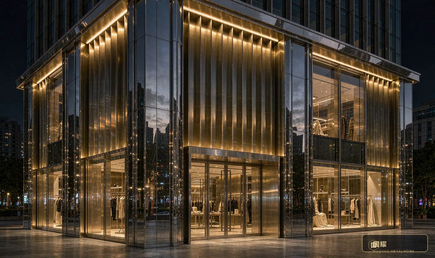
Luxury boutiques, high-end residences and luxury hotels ask different things of architectural metalwork, yet they share one underlying logic: millimetre-level dimensional control, a reproducible surface finish, and a demountable dry-hung structure. This handbook takes 12 process steps, 28 control points and 6 joint details as its spine, breaking down the complete chain from factory prefabrication to on-site assembly, with material parameters, defect prevention and acceptance standards.
Headline figures for the whole system:
- Base materials: 316 stainless steel / brass H62 / aluminium honeycomb
- Surface treatment: PVD vacuum coating
- Fixing system: back-bolt hanging · snap-fit tight joint
- Joint tolerance: ≤ 0.3 mm
- Colour control: ΔE ≤ 0.8
- Main process nodes: 12 steps
- Process control points: 28
- Boutique joint tolerance: ±0.3 mm
- PVD film thickness range: 0.3–0.5 μm
- Typical delivery cycle: 8–14 weeks
- Surface-finish warranty benchmark: 15 years
1. Process Priorities Across the Three Application Scenes
One metalwork logic, three very different demands on precision and appearance. The scene sets the tolerance grade, the surface treatment and the structural system — choose the wrong direction and no amount of site work can recover it later.
1.1 Luxury Retail Flagship
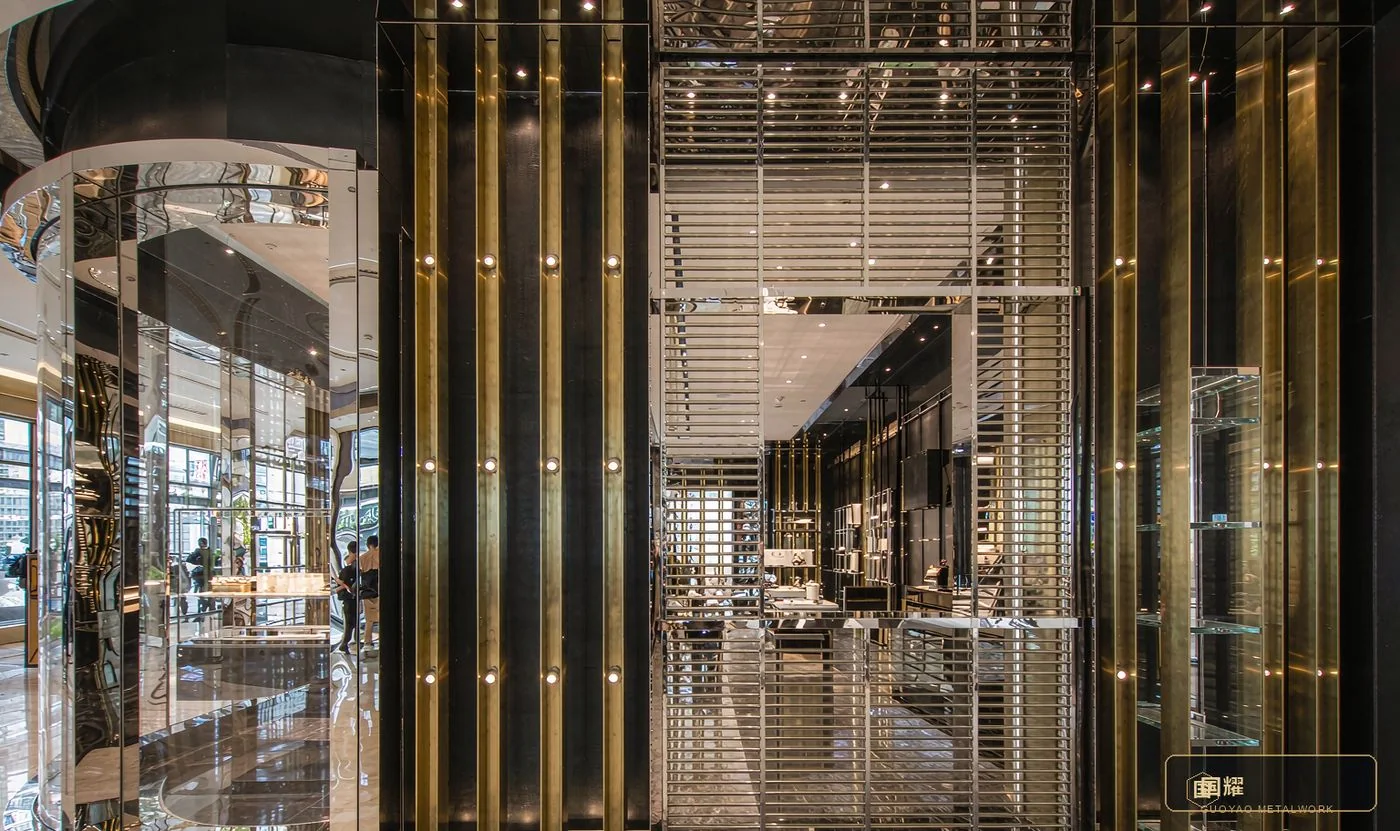
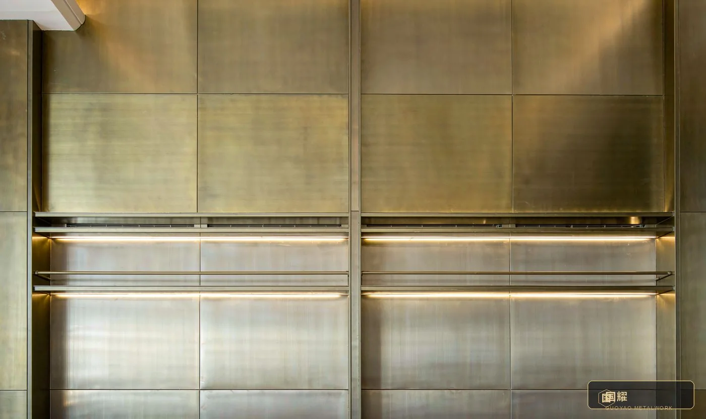
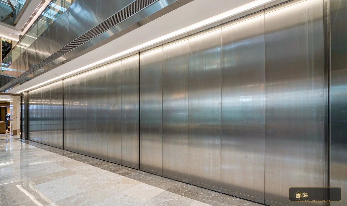
The facade is the brand. Metal louvres, mirror stainless steel and brass trim must survive close scrutiny under strong spotlights — any ripple, colour shift or misaligned joint is magnified until it glares.
- 8K mirror plus fine short-grain brushing — distortion-free reflection with no visible ripple head-on
- Joints ≤ 0.3 mm — tight joints grain- and colour-matched, seam lines dead straight
- Back-bolt dry hanging — individual panels replaceable to keep up with brand refreshes
- CNC-formed double-curved panels — seamless transitions across curved geometries
- Concealed light coves integrated with the metalwork — light without visible fittings
1.2 Premium Residence
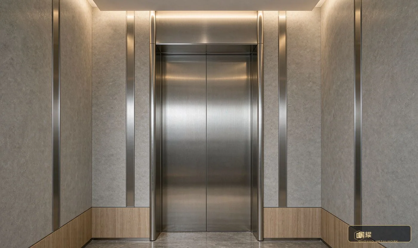
Residential metalwork is sparing but precise: skirtings, door casings, wall inlay strips and stair handrails. What matters is feel and warmth — matte, never glaring, blending naturally into timber veneers and stone.
- Long-grain brushing plus anti-fingerprint coating — a warm touch that never feels cold
- Snap-fit installation — build-up as thin as 12 mm so no space is lost
- Where metal meets stone or timber, a finished transition detailed with a 3 mm shadow groove
- Rounded outer corners R2–R5 — no sharp edges, safe to the touch
- Used as accents rather than large fields, avoiding visual fatigue from wide high-reflection surfaces
1.3 Luxury Hospitality
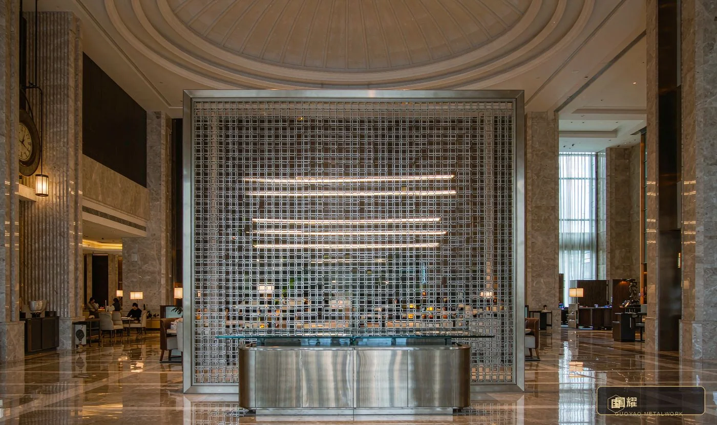
Lobbies, lift lobbies and corridors mean large areas, many batches and heavy wear in public zones. The goals are batch-to-batch consistency and long-term fingerprint and scrub resistance.
- Etched and embossed textures — scratch-resistant and touch-tolerant
- Batch colour difference ΔE ≤ 1.0 — colour locked by coating each batch in one furnace run
- Hung panels plus tight joints — any panel removable whole for maintenance
- Nano coating — anti-fingerprint, corrosion-resistant, easy to clean
- Large areas need expansion joints to absorb thermal movement
2. Materials and Surface Treatment System
The base material decides strength and weathering; the surface treatment decides texture and lifespan. Both must be locked at the sample-approval stage — changing either mid-project shifts the colour of the whole batch, the single most common cause of rework in metalwork.
2.1 Base Material Selection
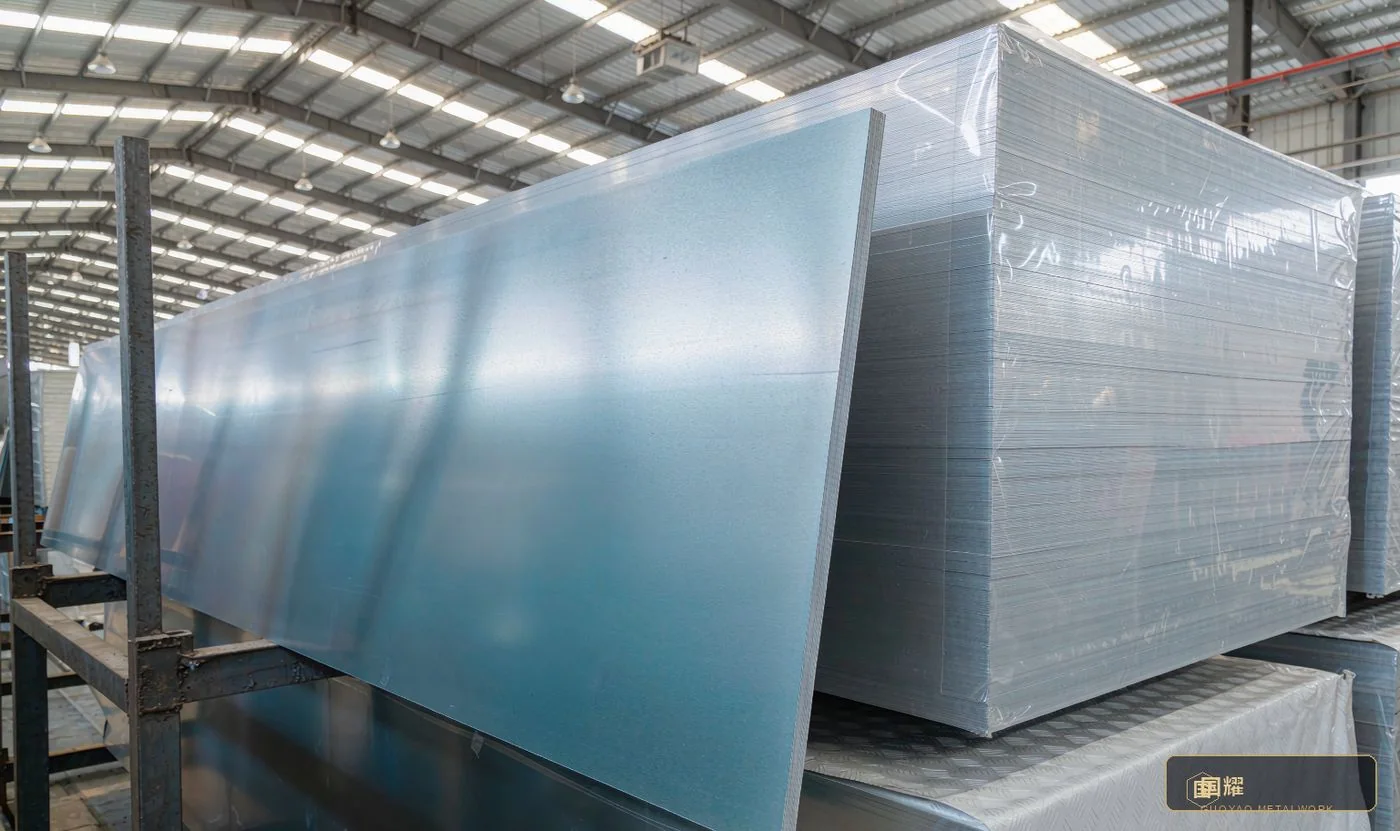
- A · Stainless steel 316 — Type: 316 stainless steel · Thickness: 0.8–3.0 mm · Salt spray: ≥ 1000 h · Best for: retail / hotel · Key trait: molybdenum-bearing, corrosion-resistant
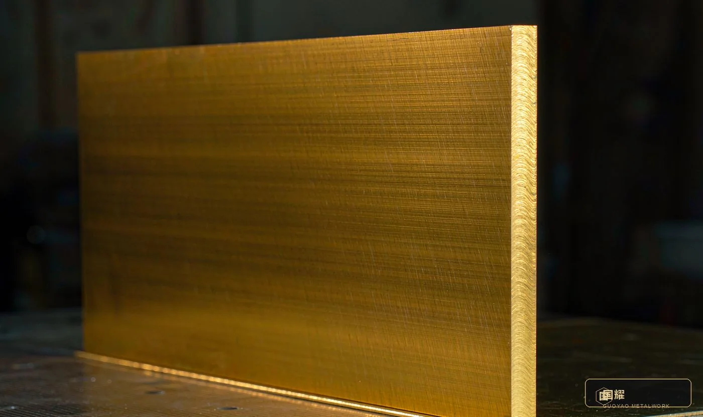
- B · Brass H62 — Type: brass alloy · Thickness: 1.0–3.0 mm · Colour: warm gold, can be aged · Best for: retail / residence · Key trait: needs anti-oxidation sealing
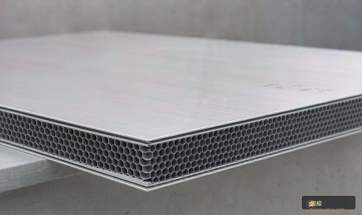
- C · Aluminium honeycomb — Type: aluminium honeycomb panel · Total thickness: 10–25 mm · Face skin: 0.8–1.2 mm · Best for: hotel / large areas · Key trait: light and very flat
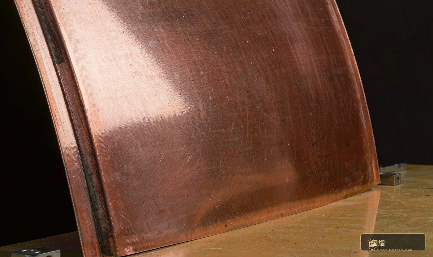
- D · Copper T2 — Type: copper T2 · Thickness: 0.8–2.0 mm · Colour: red-copper, can be patinated · Best for: residence / hotel · Key trait: needs a sealing coat
Key point: the base material and its finish must be locked together at sample approval — a late change of either resets the colour of the entire batch.
2.2 Surface Finish Comparison
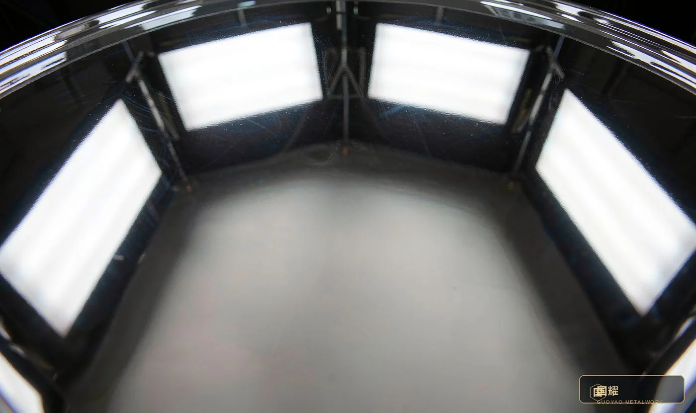
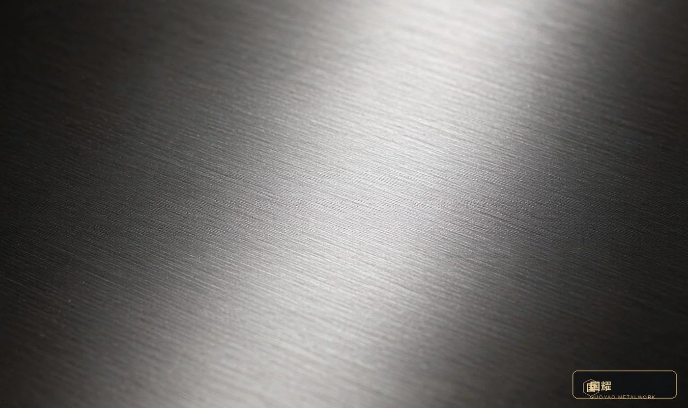
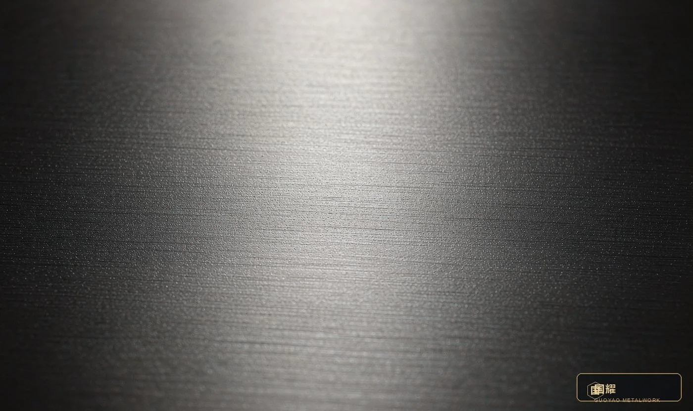
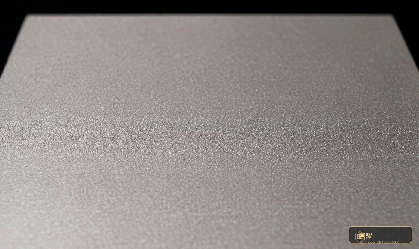
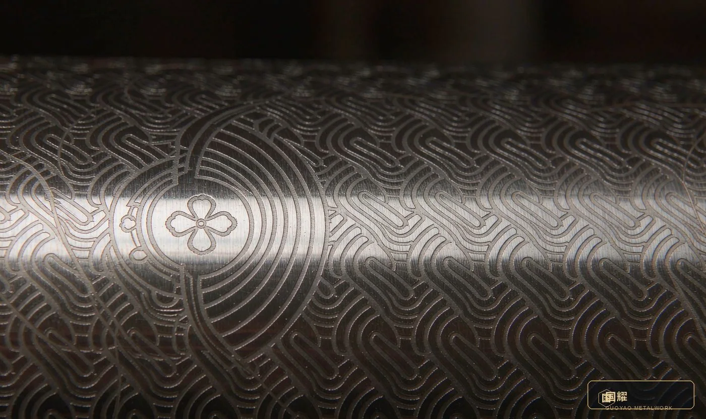
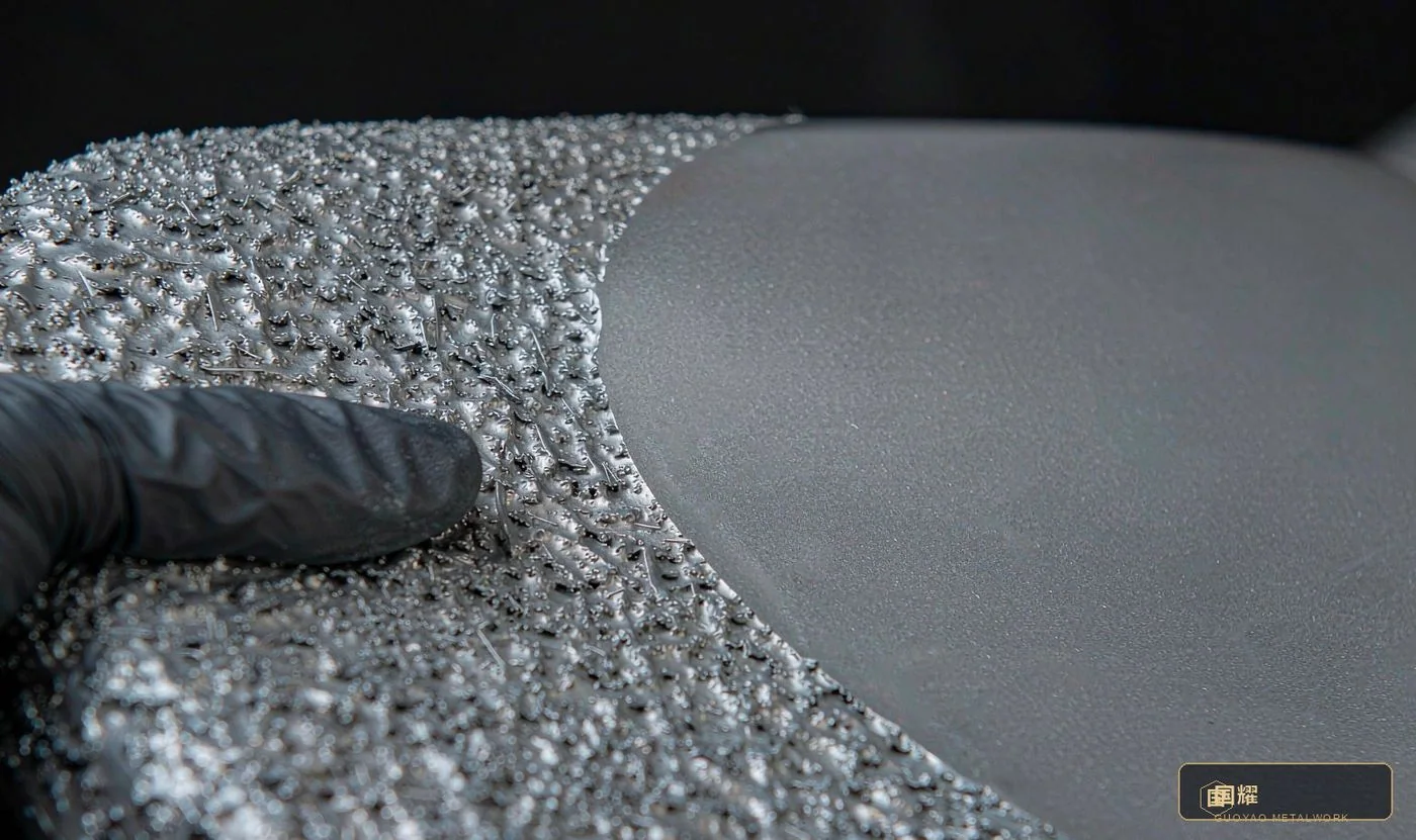
Gloss level is the first thing the eye reads, and it is the parameter most often left unquantified on drawings. Measured in 60° gloss units (GU), higher values reflect more. Luxury boutiques take the high end, residences the mid-to-low end, hotels grade it zone by zone.
- 8K mirror polish — 96 GU · Ra ≤ 0.01 μm
- Fine short-grain brushed — 52 GU · Ra 0.30 μm
- Long-grain brushed (snow-fine) — 38 GU · Ra 0.50 μm
- Matte shot-blasted — 12 GU · Ra 1.20 μm
- Chemical etched texture — 6 GU · Ra 2.00 μm
- Shot-blasted + nano coating — 3 GU · Ra 2.50 μm
2.3 PVD Colour Options
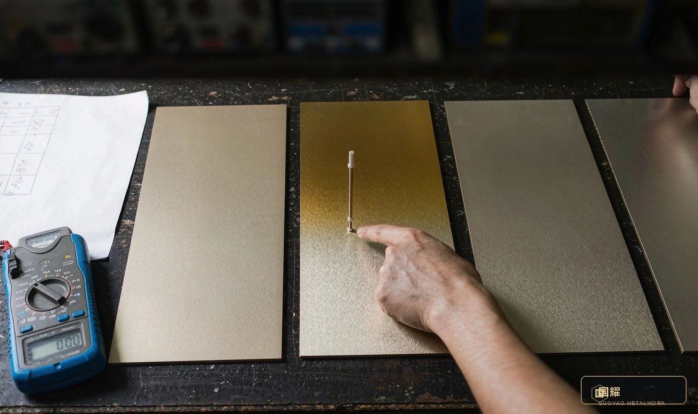
PVD vacuum coating gives a film of 0.3–0.5 μm and a hardness of HV 1500–2500. Colours must be approved against physical sample boards at the sealing-sample stage — screen and render previews will not hold the tone.
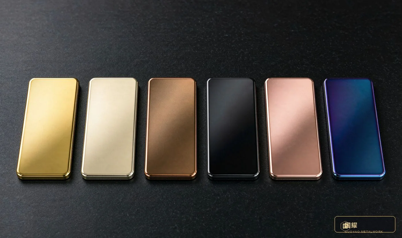
- Colours, left to right — Gold TiN (classic gold) · champagne gold · bronze · black titanium · rose gold · blue titanium
- Film — 0.3–0.5 μm
- Hardness — HV 1500–2500
- Salt spray — ≥ 500 h
- Approval — colours approved against physical boards only
Key point: PVD colour is fixed by the furnace run, not by the recipe on paper — always keep the sealed board and check incoming panels against it.
2.4 Cost Structure
For mid-to-high-end architectural metalwork, total cost taken as a 100% baseline (design fees excluded). Material plus surface treatment is about 60% — the heart of cost control.
- Sheet metal and profiles — 42%
- Factory fabrication — 20%
- Surface treatment and coating — 18%
- Site installation labour — 12%
- Packing, transport and other — 8%
The factors that move the total cost, and by how much:
- Sheet thickness — +18%
- Surface-finish grade — +22%
- Joint tolerance — +14%
- Curved or shaped work — +26%
- Larger batch — −8%
- Compressed schedule — +16%
3. Metal Assembly and Fit-Out: 12 Main Process Steps
The first six steps happen in the factory (prefabrication), the last six on site (assembly). The higher the prefab ratio, the shorter the site programme and the tighter the control. Every step lists its control points and common pitfalls.
3.1 Phase 1 · Factory prefabrication (W0–W5)
Step 01 — Site survey and design development
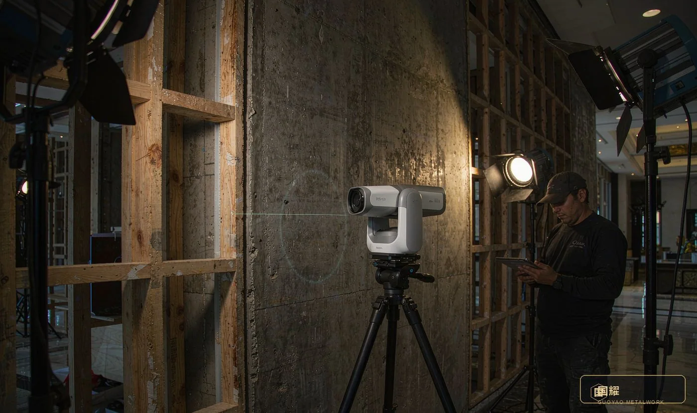
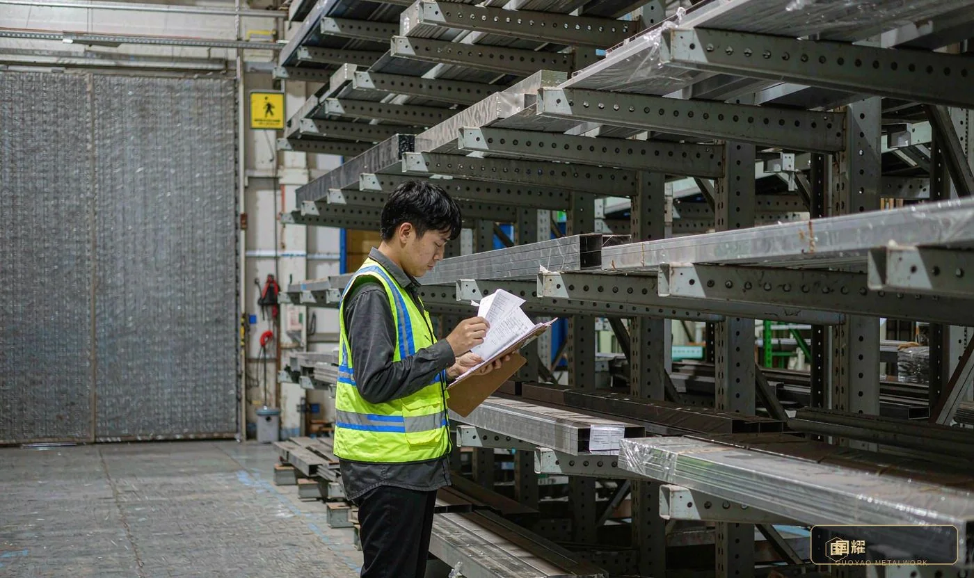
3D laser scanning captures the true dimensions of the substrate; a BIM / Rhino model then produces the panel layout, detail drawings and fabrication tickets. Every joint position is frozen at this stage — the site may fine-tune within tolerance, never re-plan.
- Deliverables — fabrication tickets, panel layout, detail drawings, bill of materials
- Control points — joints kept out of the centre of sight; panel weight ≤ 35 kg; expansion-joint positions reserved
Step 02 — Material selection and sample approval
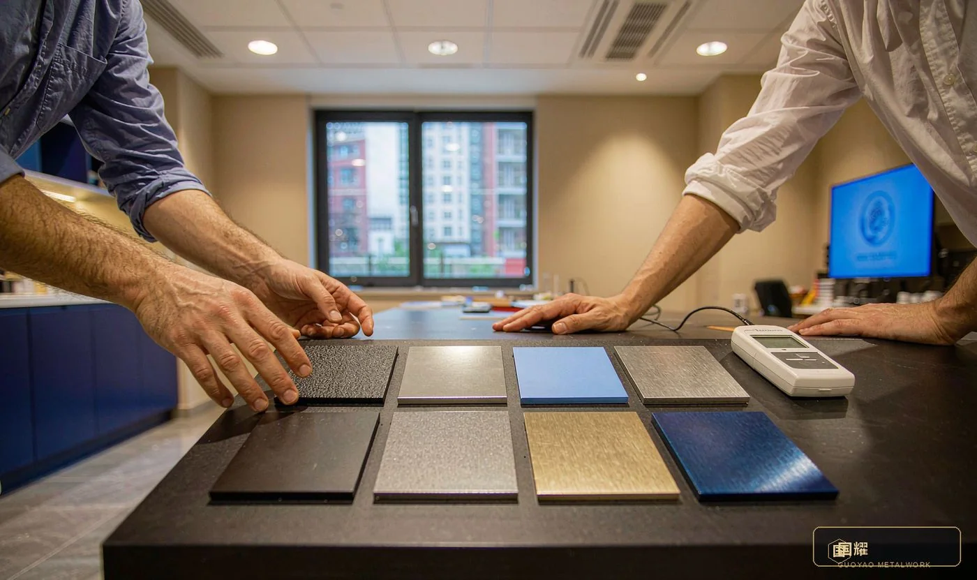
Fix the grade, the thickness and the surface treatment, then make 300 × 300 mm physical samples and approve them under the actual site lighting. Showroom and site colour temperatures differ enough to mislead the eye.
- Deliverables — three signed sealed sample sets (owner / designer / contractor, one each)
- Control points — sealed samples labelled with batch numbers; colour meter records the ΔE baseline
Step 03 — Factory cutting, bending and welding
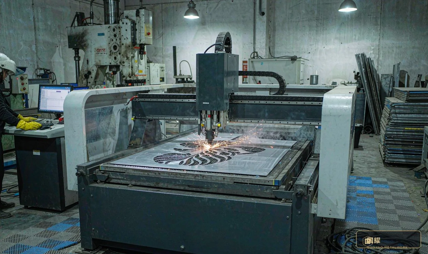
CNC laser cutting (accuracy ±0.1 mm), press-brake forming, and TIG or laser welding as required. Deslag immediately after welding so oxide tint never creeps into the base metal, and coordinate bend lines with the brushing direction.
- Equipment — fibre laser cutter, CNC press brake, TIG welder
- Control points — bend radius matched to sheet thickness (R ≥ 1.5t) to prevent orange peel and cracking
Step 04 — Weld grinding and reshaping
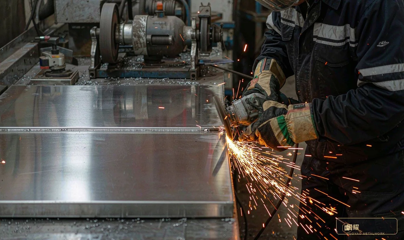
Grind welds grit by grit (coarse → fine → polish) to remove bumps and colour shift, then flatten the panel overall and control flatness. This step decides whether a mirror surface distorts like a funfair mirror.
- Tools — angle grinder, belt sander, polishing wheel, levelling press
- Control points — checked with a 1 m straightedge, flatness ≤ 0.5 mm/m; mirror panels get a reflection test
Step 05 — Surface treatment and coating
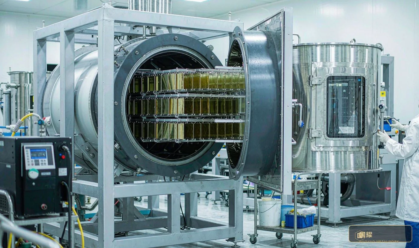
Brushing, mirror, shot blasting or etching, followed by PVD vacuum coating for colour. One batch must be coated in a single furnace run to hold colour difference. Inadequate pre-treatment cleaning is what makes the film peel.
- Equipment — brushing machine, polishing machine, PVD vacuum coater
- Control points — batch colour difference ΔE ≤ 1.0; film 0.3–0.5 μm; cross-hatch adhesion class 0
Step 06 — Film, packing and logistics
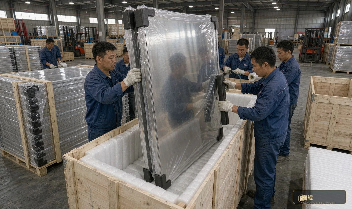
PE protective film over the surface, corner guards on all four edges, and transport upright in timber crates — never stacked flat. Every panel carries a QR code that looks up its machining parameters and installation position, and pearl cotton separates the panels in transit.
- Packing — PE film + pearl cotton + timber crate + corner guards
- Control points — upright transport; crate weight ≤ 800 kg; packing list and QR codes attached
3.2 Phase 2 · Site assembly (W6–W12)
Step 07 — Site setting-out and substrate re-check
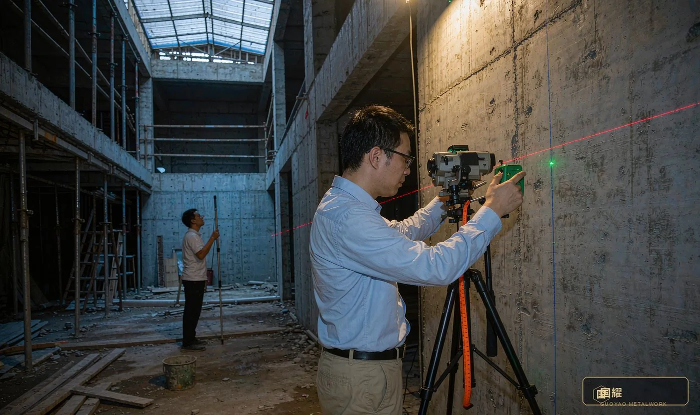
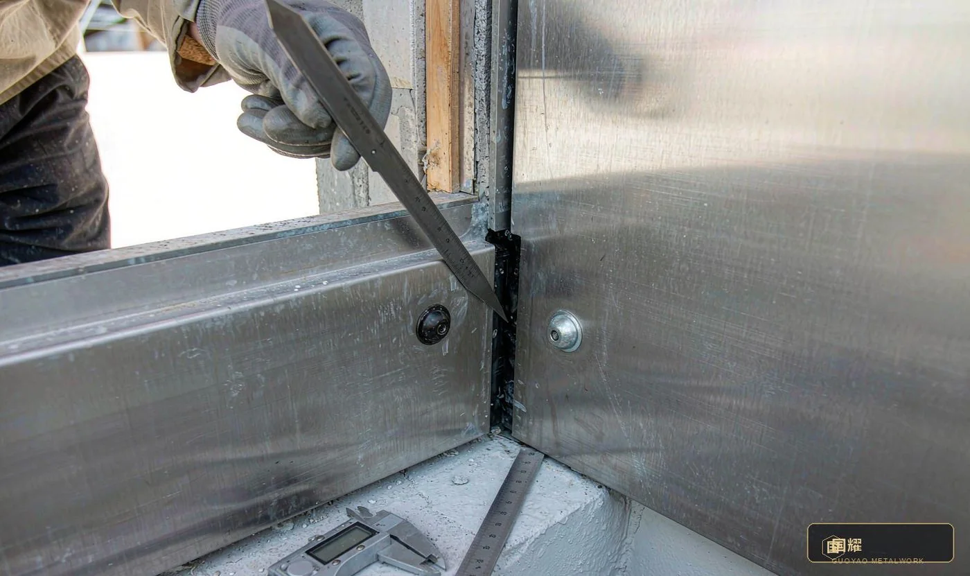
Snap out the control lines (level, plumb, offset) from the developed drawings, then re-survey the civil substrate. Anything beyond tolerance must be levelled first — never force metal panels to absorb substrate error, which misaligns the joints directly.
- Tools — laser level, total station, straightedge, feeler gauges
- Control points — substrate flatness ≤ 3 mm/2 m; plumb ≤ 3 mm; rectify first if exceeded
Step 08 — Framing and steel substructure
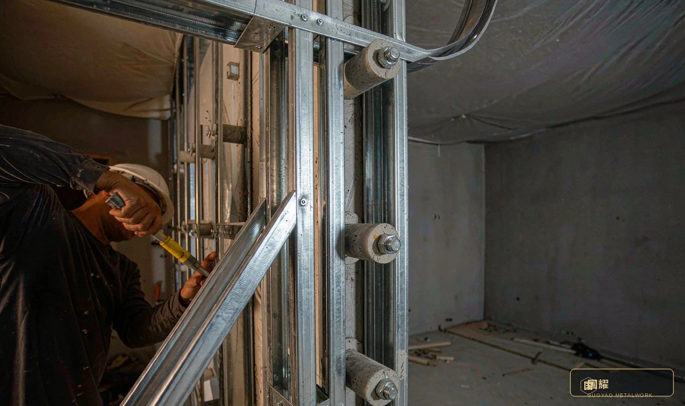
Fix vertical and horizontal framing (square steel or aluminium profiles) to the structural wall with cleats and chemical anchors. Framing centres are typically 400–600 mm and must be adjustable in three dimensions, leaving tuning range for the panels.
- Materials — 40 × 40 square steel / aluminium profiles, chemical anchors, cleats
- Control points — framing offset adjustable ±15 mm; plumb ≤ 2 mm; anchor pull-out capacity verified
Step 09 — Panel installation
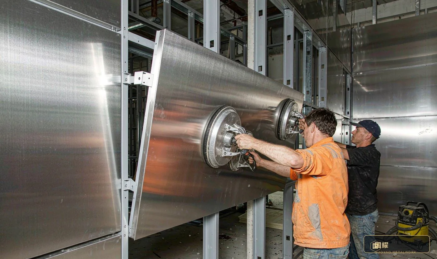
Back-bolt hanging, aluminium brackets or snap-fit, working outwards from the datum line. Re-check joints and flatness every 5–8 panels so error never accumulates to a point where the end cannot be closed. Install in the closure direction.
- Sequence — fields before closures; top before bottom; centre outwards to both sides
- Control points — joint width variation ≤ 0.2 mm; lipping between panels ≤ 0.3 mm; seam lines straight through
Step 10 — Closure, sealant and joint adjustment
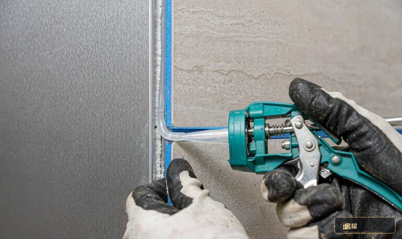
Tight joints take no sealant — precision alone controls them; open joints use colour-matched silicone or a backing rod. Internal corners, external corners and junctions with stone or timber veneer need dedicated detailing to prevent later cracking.
- Materials — neutral silicone, backing rod, masking tape
- Control points — sealant lines even in width; smooth bead, no bubbles; colour-matched silicone checked against a sample board
Step 11 — Cleaning and protection of the finished work
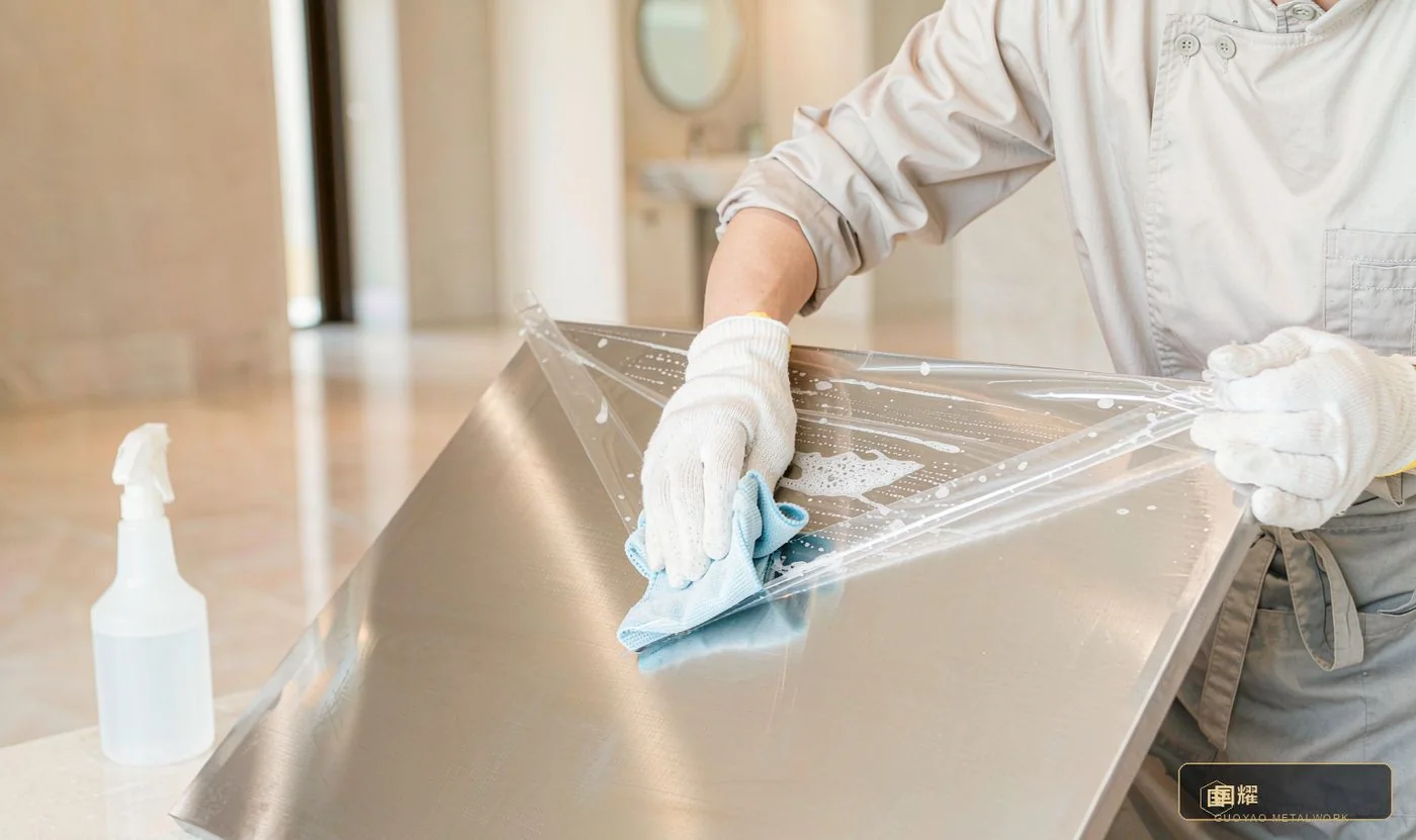
Peel the protective film (after 30 days, soften it first to avoid adhesive residue). Cleaners must be neutral — never chlorine or strong alkali, which destroy the PVD film and the brushed grain.
- Cleaning — neutral cleaner plus microfibre cloth; no steel wool, no scouring pads
- Control points — protective film kept ≤ 30 days; inspect for scratches immediately after cleaning
Step 12 — Handover and maintenance briefing
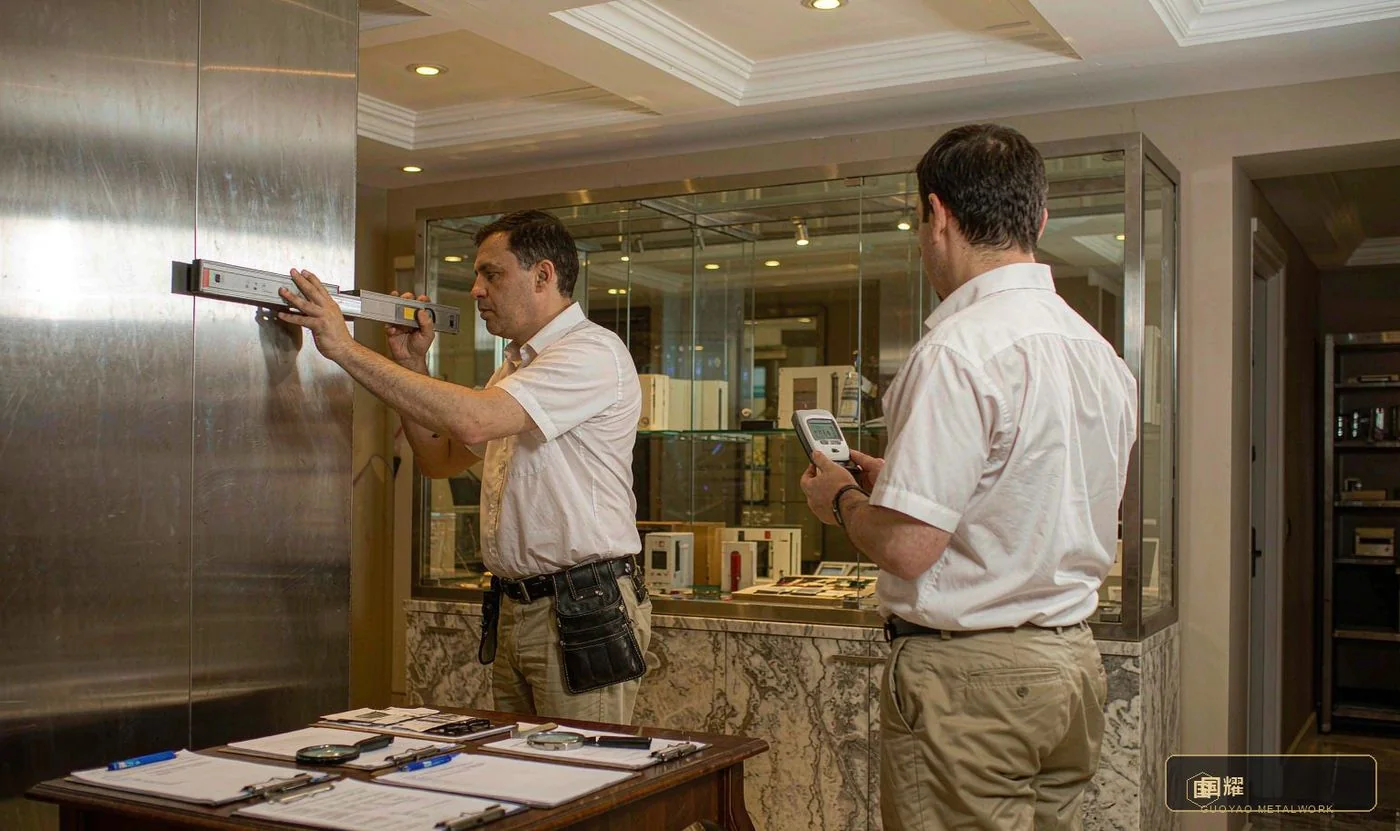
Accept against the sealed samples, recording colour difference, joints and flatness. Hand the owner a maintenance manual: cleaning frequency, approved cleaner list, single-panel replacement method, and where the spare panels are stored.
- Handover items — acceptance report, photo record, maintenance manual, spare panels
- Control points — as-built photo record kept; spare panels ≥ 3% from the same batch; maintenance briefing signed
Key point: the higher the prefabrication ratio, the shorter the site programme, the tighter the control and the lower the rework.
4. Six Key Joint Details
Details decide success or failure. The six most common ways of fixing metal panels to the substrate directly determine joint precision, demountability and cost. Each must be finalised at design development stage.
4.1 ① Back-bolt hanging
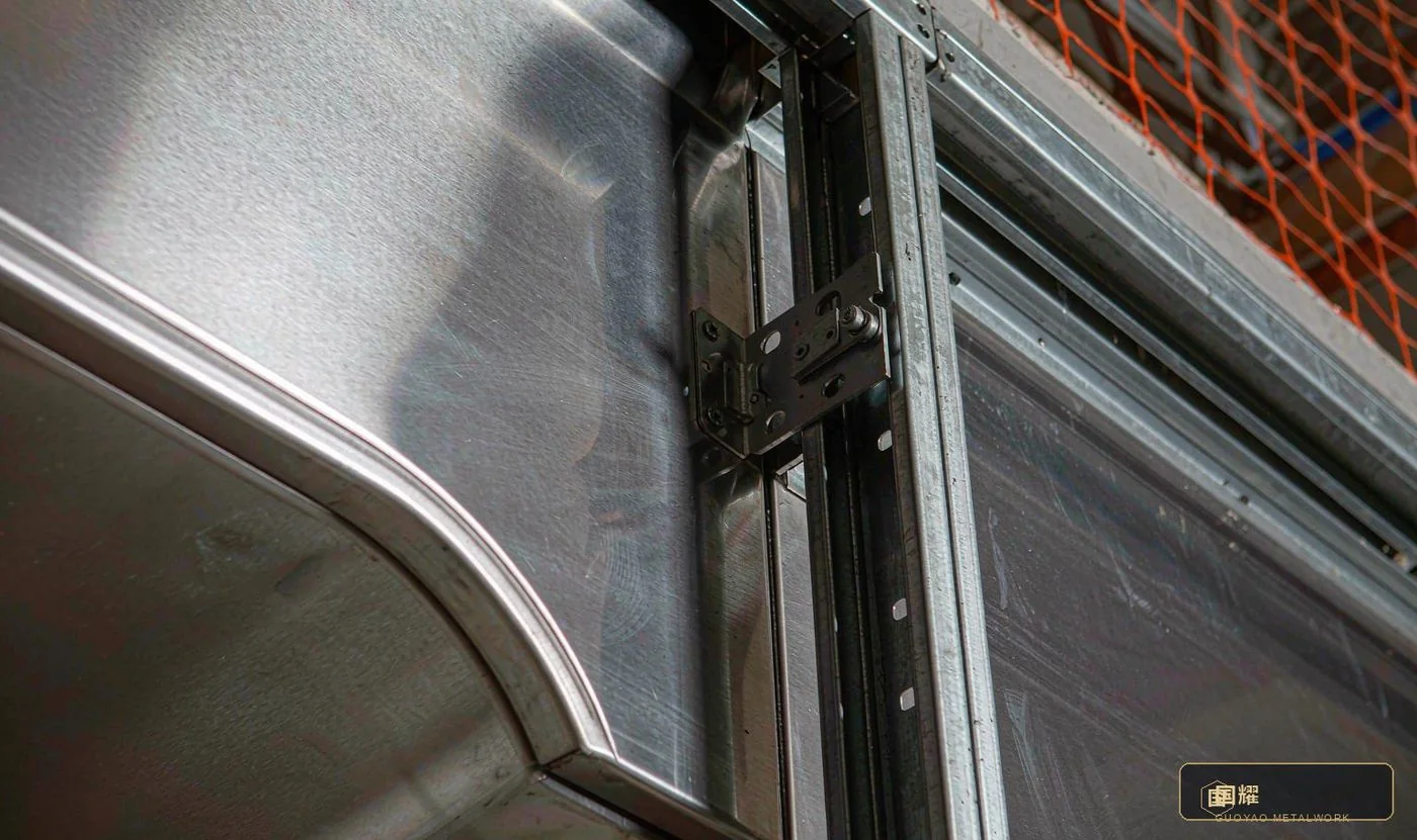
Panels hang on aluminium brackets from the vertical framing and are adjustable in three dimensions. Any single panel can be removed independently — ideal where brand graphics will be swapped or local repairs are expected.
- Cavity — 50–80 mm
- Adjustment — ±15 mm
- Best for — retail / hotel
- Removal — panel by panel
4.2 ② Snap-fit tight joint
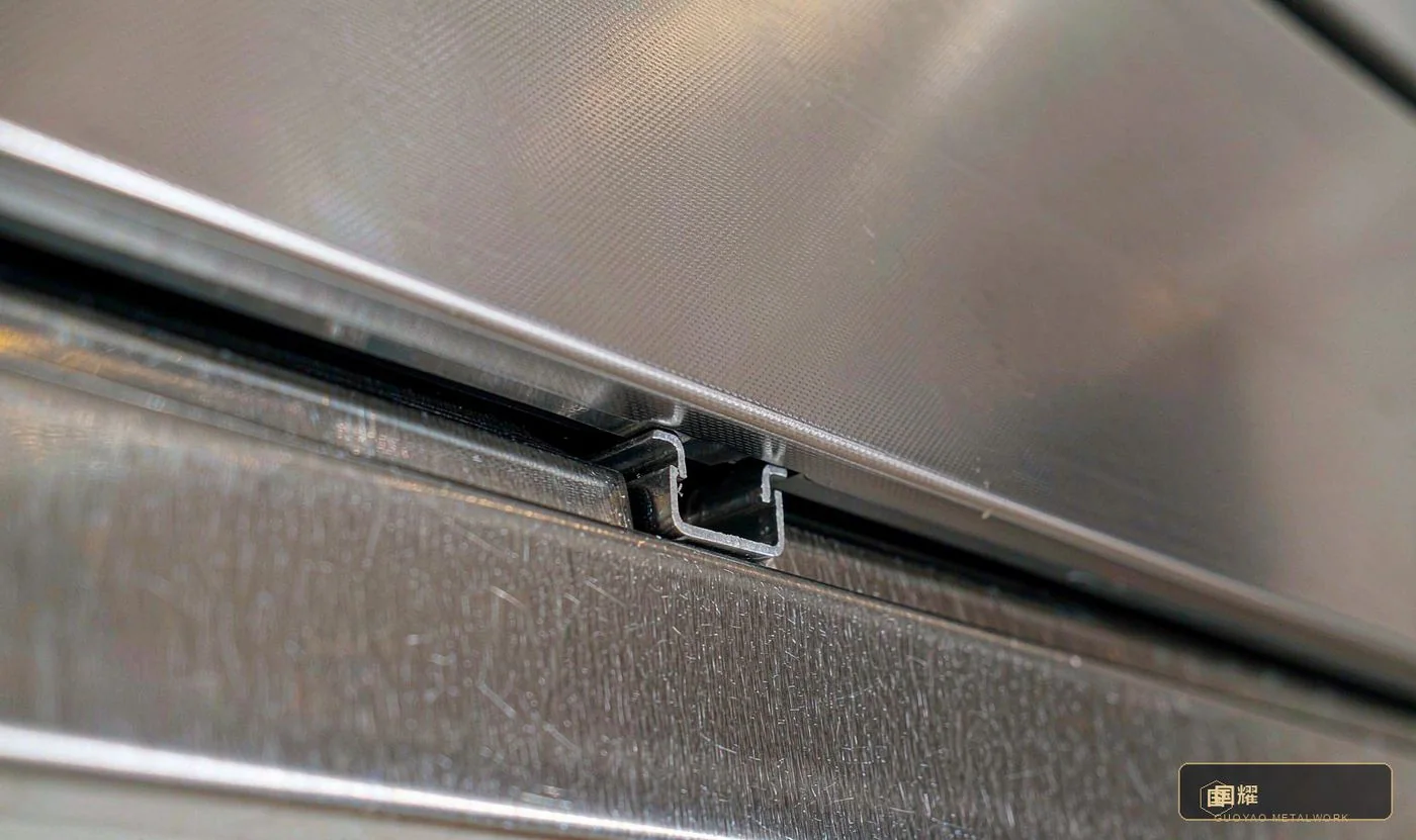
U-shaped clips pre-fitted to the panel backs snap straight onto aluminium profiles on the substrate board. Total build-up is only 25–30 mm — space-saving and fast to install, but panels must be slid out one by one from the end.
- Build-up — 25–30 mm
- Joint — ≤ 0.5 mm
- Best for — premium residence
- Removal — slide out one by one
4.3 ③ Outer corner
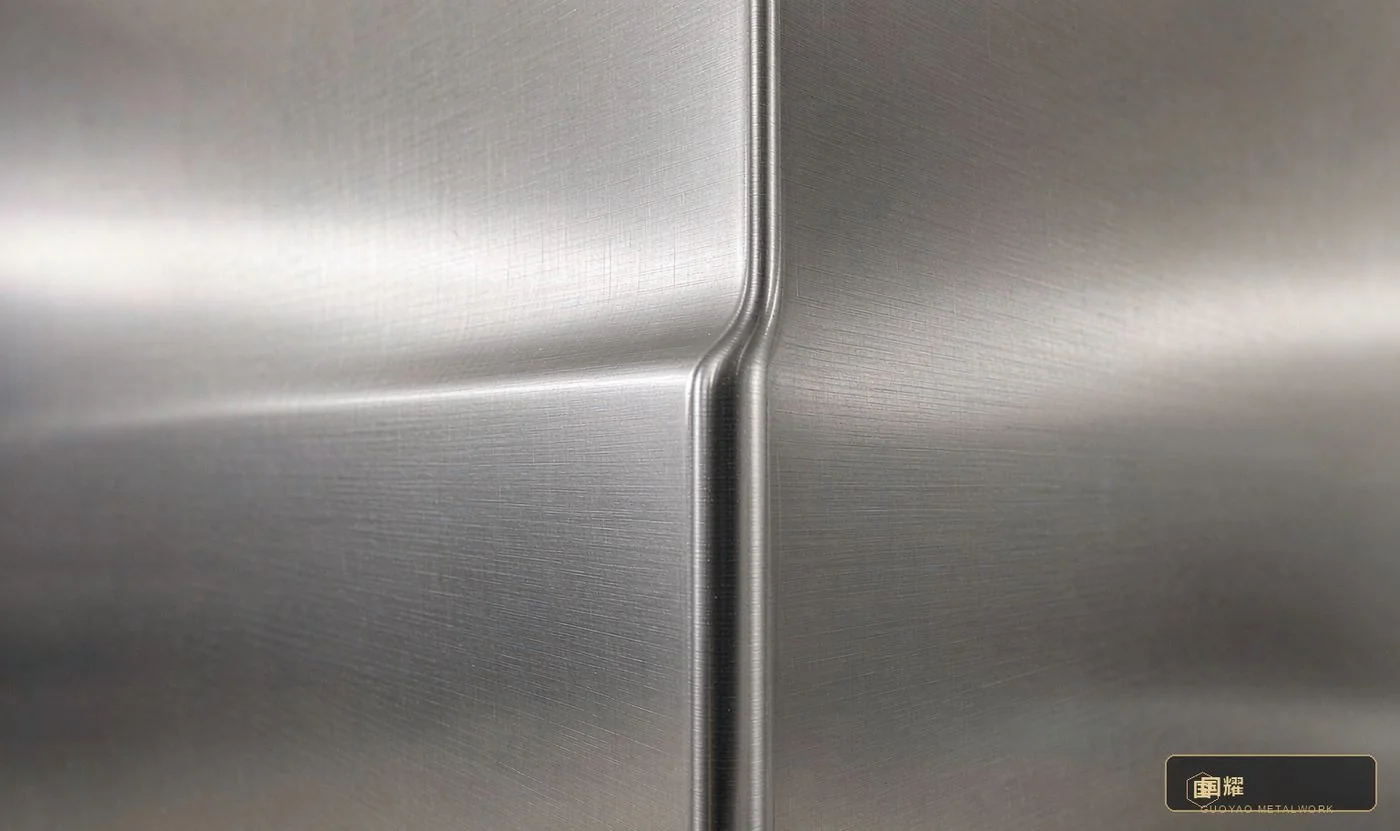
Form corners from a single folded panel wherever possible instead of butting two. The R2–R5 fold radius avoids sharp edges and softens the break in the highlight reflection. If a joint is unavoidable, keep it at least 50 mm off the corner.
- Radius — R2–R5
- Joint offset — ≥ 50 mm
- Method — single-panel fold
- Best for — all scenes
4.4 ④ Junction with stone
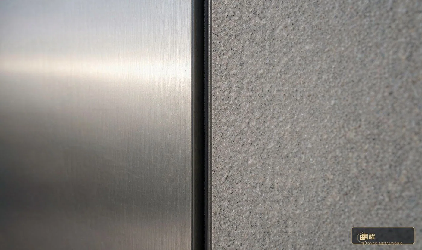
Metal and stone expand at very different rates (aluminium 23 × 10⁻⁶ versus stone 6 × 10⁻⁶); butting them hard will crack under temperature swings. Always leave a 3 mm shadow groove, filled with elastic sealant or left open.
- Groove — 3 mm
- Fill — elastic sealant / open
- Expansion gap — ≈ 4×
- Best for — retail / residence
4.5 ⑤ Expansion joint
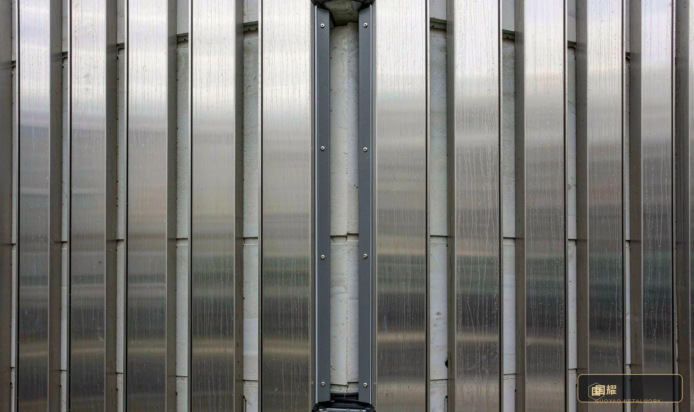
Metal expands strongly, so large continuous finishes must be broken by expansion joints. 15–20 mm wide with a sliding cover plate above — the cover hides the gap while the panels move freely.
- Joint width — 15–20 mm
- Spacing — 6–8 m
- Cover plate — sliding
- Best for — hotel / large areas
4.6 ⑥ Concealed light cove
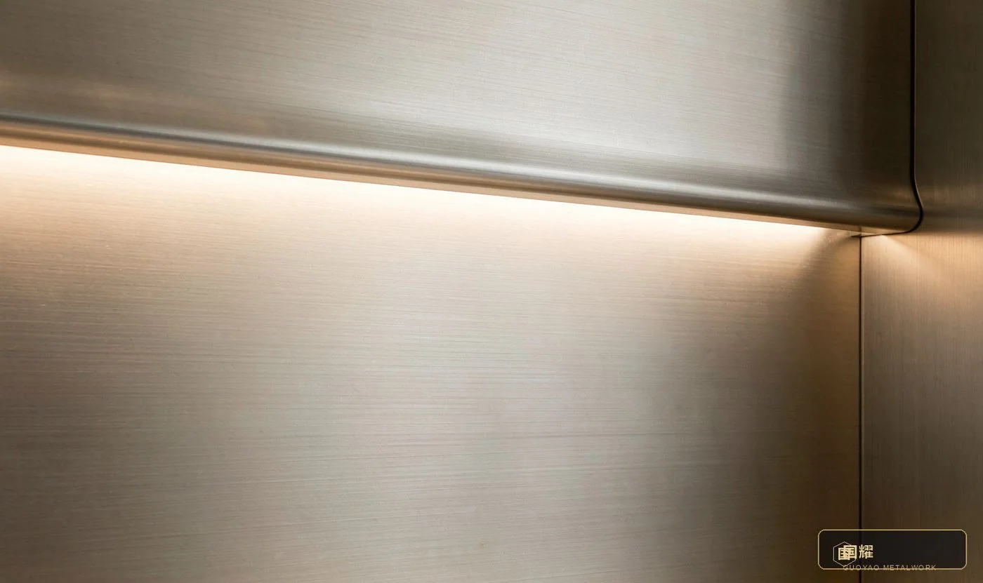
Metalwork and lighting designed as one. The panel folds 40 mm to form the cove and the LED strip hides inside; light diffuses off the metal surface for a wall-wash effect with no visible fitting.
- Fold height — 40 mm
- LED strip — 24 V
- Colour temperature — 2700–3500 K
- Best for — retail / hotel
5. Typical Programme (12 Weeks)
Factory prefabrication and site works partially overlap — that overlap is the key to compressing the programme. Site setting-out must be briefed and completed before factory cutting starts, or the fabrication tickets can never be finalised.
5.1 Programme and process timeline
Horizontal axis in weeks; bar length shows each step's duration. Gold deepens to pale with stage progress, and diamonds mark the key milestones.
- Factory prefabrication, W0–W5 — setting-out briefing → sample approval → cutting, bending and welding → grinding → surface treatment → packing and logistics
- Site assembly, W6–W12 — setting-out and re-check → framing → panels → closures → cleaning → handover
- Overlap — the two phases partially overlap
- Key milestones — sample freeze · site mobilisation · handover
Key point: site setting-out must be briefed before factory cutting begins, otherwise the fabrication tickets cannot be frozen.
5.2 Thermal expansion data
Linear expansion coefficients (units 10⁻⁶ / K). The higher the value, the more the material moves with temperature — and the more it needs expansion joints.
- Aluminium — 23
- Brass — 19
- Stainless steel — 17
- Glass — 9
- Stone — 6
Movement of a 6 m panel over a 40 K temperature swing, by material (mm):
- Aluminium — 5.52 mm
- Brass — 4.56 mm
- Stainless steel — 4.08 mm
- Glass — 2.16 mm
- Stone — 1.44 mm
5.3 Failure modes
Typical distribution of after-sales issues in architectural metalwork — colour difference and joints together account for more than half.
- Colour difference — 32%
- Uneven joints — 20%
- Scratches — 14%
- Poor flatness — 12%
- Film peeling — 10%
- Other — 12%
6. Common Defects and Prevention
These six problems account for over 80% of after-sales complaints in architectural metalwork. Spotting the causes and defending early in the process costs an order of magnitude less than repairing afterwards.
6.1 Colour difference
Different sheet batches, different coating furnace runs, uneven PVD film or inconsistent brushing depth all shift the colour between adjacent panels.
- Prevention — buy one area's panels from one batch; coat PVD in one furnace run; archive the sealed samples and compare every panel's colour-meter data on arrival
6.2 Uneven joints
Cumulative cutting errors, bend-angle deviation, installing without working out from the centre, and uneven substrates that throw panels out of line.
- Prevention — hold cutting tolerance to ±0.1 mm; work outwards from the datum line; re-check the joints every 5–8 panels
6.3 Surface scratches
Film peeled too early, panels stacked in transport, tool knocks during installation, or hard scouring pads and steel wool when cleaning.
- Prevention — keep the film on until handover; transport upright; pad installation tools with soft sleeves; clean with microfibre cloth only
6.4 Poor flatness
Sheet too thin, folded edges too soft, framing spaced too wide, weld heat distortion never flattened, or panels forced onto an uneven substrate.
- Prevention — sheet ≥ 1.2 mm; framing centres ≤ 600 mm; flatten after welding; rectify the substrate before installing if out of tolerance
6.5 Film peeling
Incomplete PVD pre-treatment cleaning, insufficient vacuum during coating, film too thin, or later attack by strong-alkali or chlorine cleaners.
- Prevention — multi-stage ultrasonic pre-treatment; film ≥ 0.3 μm; cross-hatch adhesion class 0; supply a neutral-cleaner list
6.6 Sealant cracking
Metal butted hard against stone with no groove, sealant with too little elasticity, or shear failure as the two materials move differently with temperature.
- Prevention — leave a 3 mm groove where dissimilar materials meet; use high-elasticity silicone; add expansion joints in large areas
7. Tools and Acceptance Standards
Craft precision depends on tool precision. The main equipment and inspection tools across the process, and the acceptance criteria for the three scenes side by side.
7.1 Tools and equipment
- Cutting — fibre laser cutter · CNC plasma cutter · guillotine shear
- Forming and bending — CNC press brake · plate rolling machine · hydraulic stretch former
- Welding — TIG welder · laser welder · spot welder
- Surface finishing — brushing / polishing machines · shot-blasting cabinet · PVD vacuum coating furnace
- Survey and setting out — 3D laser scanner · total station / laser level · straightedge / feeler gauges / vernier caliper
- Inspection — colour meter (spectrophotometer) · coating thickness gauge · cross-hatch adhesion cutter
- Installation — chemical anchor gun · torque wrench · suction cups / vacuum lifter
- Cleaning and protection — neutral cleaner · microfibre cloth · PE protective film / pearl cotton
7.2 Acceptance criteria by scene
- Base materials — Luxury Retail Flagship: 316 stainless / brass H62 / aluminium sheet · Premium Residence: 304 stainless / copper / aluminium honeycomb · Luxury Hospitality: 304 / 316 stainless / aluminium panel
- Sheet thickness — Luxury Retail Flagship: 1.5–3.0 mm · Premium Residence: 1.0–1.5 mm · Luxury Hospitality: 1.5–2.5 mm
- Surface finishing — Luxury Retail Flagship: 8K mirror / fine brushing / PVD coating · Premium Residence: long-grain brushing / matte / anti-fingerprint · Luxury Hospitality: brushing + etching / embossing / nano coating
- Joint tolerance — Luxury Retail Flagship: ≤ 0.3 mm · Premium Residence: ≤ 0.8 mm · Luxury Hospitality: ≤ 0.5 mm
- Surface flatness — Luxury Retail Flagship: ≤ 0.5 mm/m · Premium Residence: ≤ 1.5 mm/m · Luxury Hospitality: ≤ 1.0 mm/m
- Lipping between panels — Luxury Retail Flagship: ≤ 0.3 mm · Premium Residence: ≤ 0.6 mm · Luxury Hospitality: ≤ 0.4 mm
- Batch colour difference — Luxury Retail Flagship: ΔE ≤ 0.8 · Premium Residence: ΔE ≤ 1.5 · Luxury Hospitality: ΔE ≤ 1.0
- PVD film thickness — Luxury Retail Flagship: 0.4–0.5 μm · Premium Residence: 0.3–0.4 μm · Luxury Hospitality: 0.3–0.5 μm
- Fixing method — Luxury Retail Flagship: back-bolt hanging + concealed cove · Premium Residence: snap-fit + adhesive hybrid · Luxury Hospitality: hung panels + tight joints
- Expansion joint spacing — Luxury Retail Flagship: ≤ 6 m · Premium Residence: ≤ 8 m · Luxury Hospitality: ≤ 6 m
- Typical programme — Luxury Retail Flagship: 6–10 weeks · Premium Residence: 4–6 weeks · Luxury Hospitality: 8–14 weeks
- Acceptance focus — Luxury Retail Flagship: photography-grade finish, no ripple head-on · Premium Residence: soft to the touch, natural transition to stone and timber · Luxury Hospitality: batch consistency, long-term stain and wear resistance
Note: values are industry reference figures; actual projects are governed by the developed drawings, sealed samples and contract technical clauses. ΔE uses the CIE Lab formula, measured under a D65 standard source.
Core principle: the final look of architectural metalwork is 70% decided by factory prefabrication precision and 30% by site installation. Every joint, panel division and closure position must be fully locked at design development and issued as fabrication tickets; the site may only fine-tune within the adjustable range — metal panels must never be used to absorb structural error.
12 process steps · 28 control points · 6 joint details · acceptance criteria for 3 scenes. Process parameters are industry reference values; actual projects are governed by the developed drawings and sealed samples.